
VALVE CALIBRATION
To check valve calibration of your control valve:
1. Remove the positioner cover and locate the + and – terminals on the green terminal block.
2. Connect your mA driver to these terminals to generate a signal.
3. Set the mA driver to 4mA – the valve should remain in its de-energized state (For Centac: Inlet valve = closed @ 4mA, Bypass valve = open @ 4mA).
4. Increase the mA signal. The valve position should begin to change. This can be seen via the valve position indicator (see pic below).
5. The following are the mA inputs and corresponding valve positions required: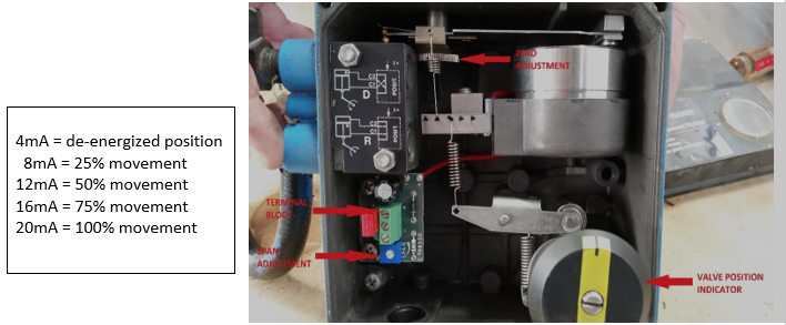
- If the valve position is not advancing according to the relationship above, an adjustment is required.
- Use “zero adjustment” to set the valve position to a specific input value.
- For example, with an input of 12mA, the valve should be @ 50%.
- Use the “span adjustment” to adjust the % change the valve moves relative to the input value.
6. Stroke the valve – Take the valve thru a complete cycle of 4 – 20 mA inputs verifying that the correct valve position exists with a given input value.